In a previous note in the series, we presented how to run ADV7180 on an i.MX6 module from Toradex. While ADV7180 is a good enough chip, it does not feature hardware deinterlacing, and we had customers ask us how to get the same effect on Toradex’ Tegra T30 module in the same format.
The video coprocessors of the Tegra T30, while powerful, do not allow to do hardware deinterlacing and so ADV7180 is not an optimal choice for this module. Instead, the chip’s successor – ADV7280 can be used.
ADV7280 is a Standard Definition TV video decoder with a built-in image deinterlacer. It decodes images from analog cameras (using a CVBS or S-Video signal) and converts it to a digital (8-bit) BT.656 YCrCb 4:2:2 output format.
Knowing all this does not really help that much without a reference design to show how it’s done. Since Antmicro works a lot with video and camera projects, we decided to make a reference board and the necessary ADV7280 driver, and feed this back to the community.
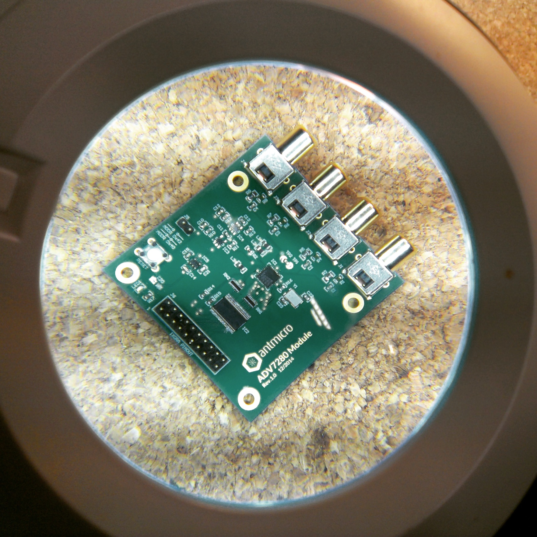
The reference board for the ADV7280 video decoder can be seen below – you can connect it to the awesome Toradex Ixora devboard like in the other picture later in the post.
The board has four analog inputs, so it is able to decode the image from four cameras (not simultaneously) using a CVBS signal or one CVBS + one S-Video camera.
Deinterlacing in brief
The video stream from analog sensors is being output line by line.
The first frame (with the same width, but half the height of the output image) consists only of even lines of the output image, the second frame – odd lines, so to view the image correctly you have to grab two frames and combine (interlace) the lines from both of them in the correct order (called ‘progressive’).
The ADV7280 video decoder does this automa(t/g)ically with the use of the I2P function (interlaced-to-progressive).
The image is also automatically filtered i.e. the artifacts (comb effects) caused by the interlacing process are removed, so there is no need to use any deinterlacing plugins/algorithms.
The gritty details
We present a brief guide on how to create a full setup to preview the image from an analog PAL camera below.
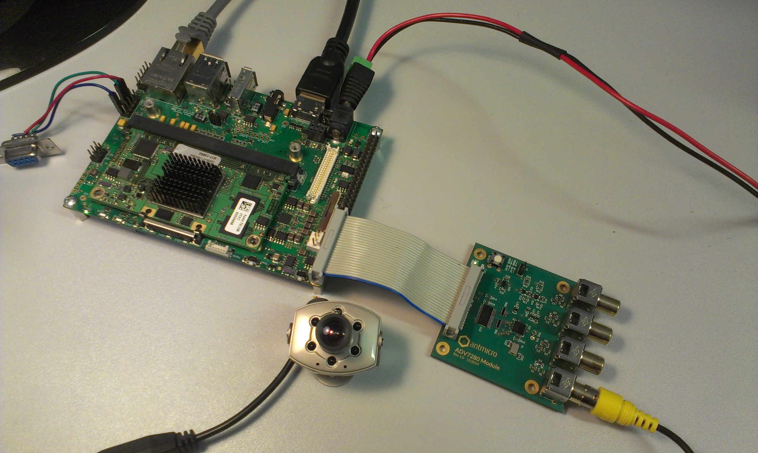
After plugging in the Apalis T30 module to the socket on the Ixora devboard as shown on the image below, connect the supply voltage, keyboard/mouse and display via HDMI output.
The ADV7280 decoder board should be connected to the devboard (X14 connector on the Ixora side, J6 on our module) using a short 20-pin ribbon cable.
Get the newest version of the Linux kernel from Toredex’s git repo (our ADV7280 patches should be there soon):
git clone git://git.toradex.com/linux-toradex.git -b tegra-next
cd linux-toradex
Configuring the kernel/drivers:
export ARCH=arm
export CROSS_COMPILE=/usr/bin/arm-linux-gnueabi-
make apalis_t30_defconfig
make menuconfig
The ADV7280 driver must be compiled as a module (find it under: Device Drivers --> Multimedia support --> Video Capture Adapters --> Encoders, decoders, sensors and other helper chips).
Compile the kernel and the drivers:
make -jX uImage  # X being typically how many threads your PC boasts+1, -j9 for us
make -jX modules # as above
After flashing the board and rebooting, copy the drivers to the module, the simpliest way is to use the scp command (after setting up the network on the Apalis module):
scp drivers/media/video/*.ko root@/ip-address-of-the-module/:~Now open the terminal and load all the required modules in the following order:
insmod videobuf2-memops.ko
insmod videobuf2-dma-nvmap.ko
insmod adv7280.ko
insmod tegra_v4l2_camera.ko
If everything is OK, you should see the output of the dmesg command, saying that the ADV7280 was detected properly:
adv7280 2-0021: chip found @ 0x42 (Tegra I2C adapter)
adv7280 2-0021: ident reg is 0x42
If your camera is connected to some other input than J1, you have to change it using v4l2-ctl --set-input x, where x is the index of an input:
- 0 – AIN1 -> J1 connector
- 1 – AIN2 -> J2 connector
- 2 – AIN3 -> J3 connector
- 3 – AIN4 -> J4 connector
Now you’re ready to preview the image from the camera:
gst-launch v4l2src ! nvvidconv ! nvxvimagesinkEnjoy! If you are interested in reproducing the reference board, the schematics and BoM will be published soon, but of course this is a fairly straightforward board.
If your project is in dire need of one, don’t hesitate to contact us – we do have a few spares.