In hardware design, thermal simulation is used to predict the heat flow between electronic components and heatspreaders, and to identify potential bottlenecks in a thermal management system, before building physical prototypes. It helps design robust cooling systems that reduce overheating risks, which is particularly important as hardware miniaturization increases the heat produced per square inch of a circuit board. This is applicable across industries such as drones, medical equipment, automotive, space, and consumer electronics.
In space applications, in particular, vacuum testing is a crucial component of thermal validation, but early-stage simulation accelerates validation and deployment. Some time ago, we described the fundamentals of our open source flow for thermal simulation and analysis that features visualizations made in Blender, which allow for clear-cut identification of any hotspots. Originally devised for a commercial project, the usefulness of our approach is already being confirmed in real-life scenarios.
In this article, we take a look at the improvements that we have since introduced to the thermal simulation’s visualization flow and its automation, as well as at the physics models for convection, with a particular focus on the film (heat transfer) coefficient.

Improvements to the rendering flow
Previously, we had used ParaView to visualize temperature changes over time in the simulation. ParaView depicts the temperatures with a color gradient on a scale, which simplifies reading the values directly. However, the visual quality of ParaView outputs is relatively low compared to what Blender’s rendering engine is capable of producing. We implemented a color gradient temperature representation in Blender that produces high-quality renders. To fully automate it, we took advantage of Antmicro’s existing open source visualization tool - PCBooth, which serves to set up a rendering scene (lights, camera parameters, etc.).
Representing temperature with a gradient and a corresponding colormap scale enabled precise and unambiguous interpretation. We also added the Fahrenheit temperature unit and a scale to the plots for improved readability.
We also introduced an automated flow which uses the FreeCad API at the first stage of the pipeline; as an added benefit, there are fewer matters that you need to see to manually, such as exporting Calculix input files and setting the Calculix configuration.
In case the predefined PCBooth cameras are not sufficient, you can define a custom camera. This enables focusing the visualization on the selected part of the design by setting the camera’s position, angle, and zoom. Camera parameters are stored in the simulation config and are later applied to every frame during rendering.
The simulation features an optional configuration file. It allows for the following actions:
- Adding user comments to the simulation report.
- Defining a custom camera for the visualizations.
- Defining search boundaries for stabilization temperature for the automatic film coefficient simulation.
- Defining surfaces orientation for the automatic film coefficient simulation.
After the simulation, a report file is automatically generated. It contains the following information about simulation setup in Markdown format:
- Material constraints
- Solver configuration
- Tools versions
- Heat source(s) parameters
- Initial temperature
- User comments
To reference more info about the Thermal Simulation Flow (scripts), visit the GitHub repository.
Simulating natural and forced convection, and vacuum environment
Another major improvement to our thermal simulation was refining the convection calculations, which now take place before the simulation is run (and rendered).
You can simulate your design in various environments, of various thermal properties (or constraints). The simulation relies on three major categories of thermal constraints: natural convection, forced convection, and vacuum environment. Both natural and forced convection are represented by the film coefficient and the heat that is transferred by the moving particles of air.

A surface’s temperature can be determined in the simulation, but we also need it to calculate the film coefficient for the same simulation. Previously, to solve this, we had run the simulation repeatedly, adjusting the input temperature each time, until it had matched the stabilized temperature of the object, received as the simulation result.
We automated this calculation using a bisection algorithm, which increases or decreases the input temperature, based on the results. It is an iterative approach, comparing the temperature assumed for the calculations with the temperature obtained from the simulation; it modifies the former until the difference fits within the tolerance margin. This approach establishes the stabilized temperature of the simulated object and was verified experimentally by comparing the simulation results with the temperature measurements.
The thermal constraints, which you can establish in FreeCAD, define the properties of the environment and components in your simulation. For details related to constraint definitions, refer to the FreeCAD docs.
Impact of conductivity and geometry on heat transfer via conduction - case study
The bottleneck design reflects a real-world scenario where a small area of the chip surface is connected to a heat absorber, from which heat is conducted to a comparatively large radiator. The junction between the small heat absorber and the large radiator is a critical part of the design. All the heat transferred from the chip to the radiator must pass through this junction.
- When the junction is designed adequately, it exhibits low thermal resistance, enabling efficient heat transfer. As a result, the temperature gradient across the junction remains minimal.
- Conversely, if the junction is poorly designed, it exhibits high thermal resistance. Heat flow is restricted, causing heat accumulation. This leads to high temperatures at the heat source and an increased temperature gradient across the junction.
The factors influencing the thermal resistance of the junction are the cross-sectional area (larger reduces the resistance), material conductivity (higher lowers the resistance), and material length (shorter decreases the resistance).
We have prepared a short case study of such a bottleneck junction, where we compared the impact of its shape and material on the heat transfer. For all simulated cases, we have assumed a vacuum environment, constant power source with a single point of contact, and that all metal solids are covered with a black, highly emissive coating (e = 0.88). This approach ensures that the heat is being radiated equally, and that the radiation factor is not altering the comparison.
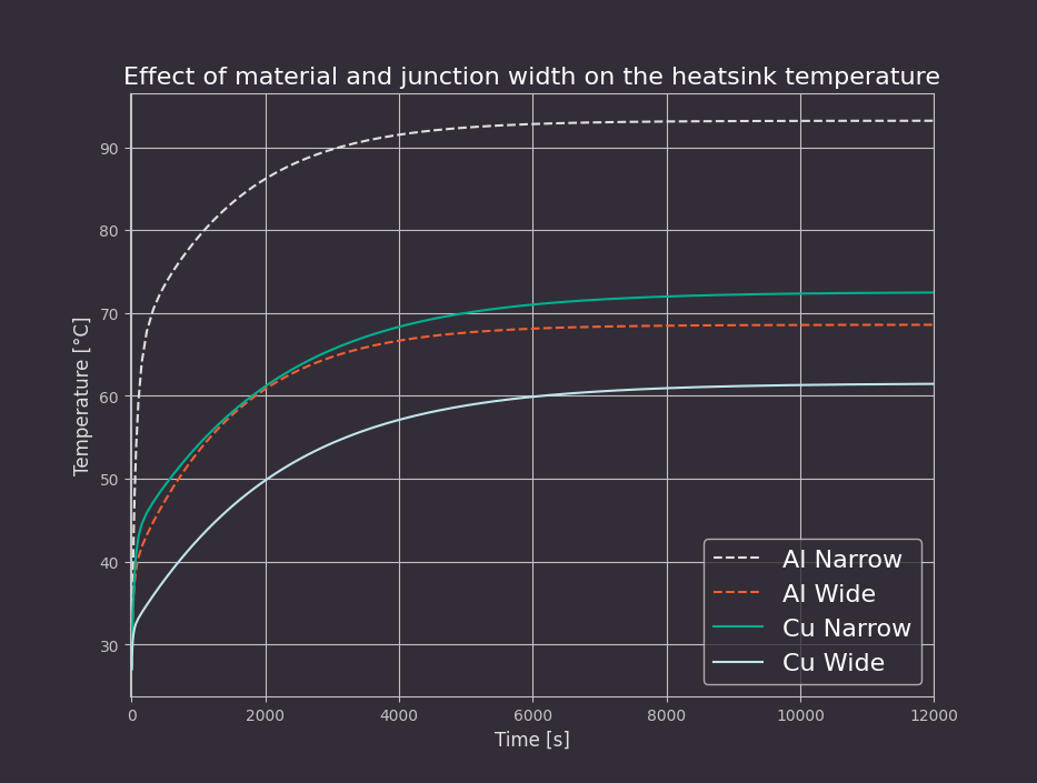
We focused on the following test cases; see the data table and descriptions with conclusions below:
| Material | Thermal conductivity (k factor) | Geometry (L×w×h) | Area | Max Temp. | Min Temp. | Difference Temp. |
|---|---|---|---|---|---|---|
| AlMgSi F31 | 92 BTU/h·ft·°F (160 W/m·K) | 30×3×10 mm | 30 mm² | 199.8 °F (93.2 °C) | 129.7 °F (54.3 °C) | 70.1 °F (38.9 °C) |
| AlMgSi F31 | 92 BTU/h·ft·°F (160 W/m·K) | 30×13×10 mm | 30 mm² | 155.4 °F (68.6 °C) | 131.6 °F (55.3 °C) | 23.9 °F (13.3 °C) |
| generic copper | 230 BTU/h·ft·°F (398 W/m·K) | 30×3×10 mm | 30 mm² | 162.5 °F (72.5 °C) | 132.8 °F (56.0 °C) | 29.7 °F (16.5 °C) |
| generic copper | 230 BTU/h·ft·°F (398 W/m·K) | 30×13×10 mm | 30 mm² | 142.6 °F (61.5 °C) | 133.0 °F (56.1 °C) | 9.7 °F (5.4 °C) |
Aluminum narrow junction solid: in this design, heat does not propagate fast enough throughout the junction. The temperature of the source side remains higher than that of the radiation area, reaching 200 °F (93 °C). This does not meet our design requirements - such temperatures may often cause integrated circuits to malfunction or throttle down.
Aluminum wide junction solid: increasing the width of the junction influences the thermal performance. The difference between the heat source and the radiator is much smaller, with a lower overall temperature maintained on the side of the heat source.
Copper narrow junction solid: changing the material that the junction part is made of is another way to improve thermal conductivity. The simulation shows that using copper, which has a higher conductivity coefficient, also reduces the temperature of the heat source.
Copper wide junction solid: combining these two approaches - changing the material and width of the junction part - yielded a design that maintains the temperature of the heat source at a safe level of 142 °F (61 °C). The temperature difference between the heat source and the radiator is reduced to 9 °F (5 °C), which indicates efficient heat transfer through the junction.
Below is the visual simulation of the tests:
In the considered test cases, both the junction material and junction width impacted thermal dissipation, resulting in differences of up to 90 °F (32 °C) in the heatsink temperature at the point touching the heat source. Since we have considered this junction as a heatsink for a computing chip featuring a working temperature of up to 185 °F (85 °C), three cases yielded acceptable results:
Testing the thermal properties of your system with Antmicro’s simulation workflow
The case study described in this article demonstrates that integrating Antmicro’s improved thermal simulation flow into the design process of heat dissipation systems can help identify risk areas with high thermal resistance. With an iterative approach incorporating simulation in subsequent design updates, the system can be tailored to reduce thermal bottlenecks. In effect, the design can be continuously improved, until its thermal performance meets the system requirements.
Antmicro’s experience with designing devices operating under extreme conditions allowed refining the thermal simulation workflow for estimating the temperature of hardware enclosures produced with different materials and in different environments. It reduces the costs associated with manufacturing and post-production testing of the physical enclosure, ultimately resulting in improved design efficiency and faster time-to-market of your product.
If you would like us to help you design your own device for a specific (extreme) environment, and then perform its thermal simulation, aiming to quickly deploy it, reach out to us at contact@antmicro.com - we will be happy to discuss your case.