Every System-on-Chip (SoC) is made of multiple components, such as CPU, memory, peripherals, and DMA, and each component exposes a bus interface (e.g. AXI, AXI Lite, AHB, APB, Avalon, TileLink, Wishbone, etc.) for data transfer. An interconnect allows for communication between different components and buses, providing features for routing traffic between peripherals according to the address map, converting bus interfaces and protocols, and handling clock domain crossing (CDC).
Designing or updating an interconnect can be time-consuming, as once it’s assembled, introducing changes may require some additional, often manual actions. To expedite and automate this process, Antmicro created Omnibus, an open source tool that allows generating interconnects from YAML specification files, populating them with all the necessary components, such as CDC or protocol converters.
In this article we describe Omnibus and the rationale behind its creation, and show how it can be used alongside our Topwrap design aggregation tool to easily create and modify concise representations of interconnect microarchitecture in a textual format.
Interconnect design
An interconnect is built using components that perform specific functions, including address decoding, traffic multiplexing and demultiplexing, protocol/interface conversion, data width conversion, clock domain crossing (CDC), and data buffers. Designing an interconnect usually starts with a list of SoC components and their communication interfaces, the clock domains they use, data throughput requirements, and the SoC address map. The next step is establishing the interconnect microarchitecture, i.e. which components to use and how to arrange and connect them. Once the microarchitecture is established, the blocks need to be connected manually in RTL code to form a complete interconnect.
This approach presents several issues: once the interconnect is assembled, changes to the microarchitecture are difficult to introduce, and changing the address map requires manual updates to the address decoder logic, which carries a risk of errors. Adding a port for a new peripheral may require redesigning an interconnect part, followed by manual component assembly, which again increases the risk of errors.
To address these issues, Antmicro developed Omnibus, an interconnect generation tool that can create complete, functional interconnects, based on easily modifiable high-level specification files.
Omnibus overview
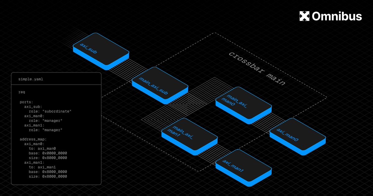
Omnibus generates complete interconnects based on YAML specification files. It allows for automatic insertion of adapter components (such as protocol/interface converters, CDC). Since the interconnect description is contained within a single file, you can easily make changes to the interconnect design and microarchitecture, and then visualize the interconnect structure for inspection and debugging. Omnibus allows for:
- full control over routing architecture through manual specification of crossbars
- automatic insertion of converters between ports with different parameters
- automatic conversion of a system wide memory map to a memory map for each crossbar
- mapping components from abstract converters into actual I/O blocks
In its current implementation, Omnibus uses components from the PULP platform, although it is not limited to them. The simplest interconnects require the user to only specify ports, address maps, crossbars, and connections. Other components like converters are inserted automatically if not manually specified in the design.
Currently, Omnibus supports two backends, the open source Graphviz tool that is used for visualization and debugging, and the Topwrap Pulp Platform that converts internal representation of the interconnects into Topwrap project files and SystemVerilog wrappers. Using Topwrap, you can then view the interconnect in the GUI and generate Verilog. Verilog files can also be generated directly from Omnibus.
To simplify Omnibus’s usage with Topwrap, we created a dedicated plugin providing all the data needed to generate top-level wrappers.
Verification
To verify Omnibus’s functionality, we created a dedicated test suite utilizing Pytest, cocotb and Verilator.
The YAML input files are verified with valid specifications that test common interconnect configurations, as well as possible syntax errors to check whether the YAML frontend correctly reports errors. Similarly, processing, i.e. establishing what is the property of each port, inserting new components, finding address maps for each crossbar, and connecting ports, is checked against golden files and expected errors. Backend tests check whether the Graphviz backend works with all display options and whether the Topwrap backend creates proper Topwrap specification and wrapper files. Each stage is verified both in isolation and as part of the full flow.
Verilator is used to check SystemVerilog syntax and to generate simulation, while cocotb and cocotbext-axi are used to run the simulation with positive and negative tests. This includes testing whether the interconnect builds correctly, checking reads and writes to all ports, including potential breaking spots such as address range edges, and checking for incorrect behavior, e.g. writing to unmapped addresses.
The AHB<->AXI bridge is verified using a UVM test suite against 3rd party verification IPs.
Generating an interconnect from a YAML file using Omnibus
To demonstrate how Omnibus generates and visualizes interconnects, we’ll use the simple example shown below, which you can also find in the Omnibus repository among other, more complex examples:
desc_version: 1.0

name: simple
version: 1.0

default:
  data_width: 64
  clock: clk
  frequency: 10MHz
  protocol: AXI4

ports:
  pin:
    role: "subordinate"
  pout1:
    role: "manager"
    protocol: AXI4Lite
  pout2:
    role: "manager"

address_map:
  pout1:
    to: pout1
    base: 0x0000_0000
    size: 0x8000_0000
  pout2:
    to: pout2
    base: 0x8000_0000
    size: 0x8000_0000
The file specifies an interconnect with one input port and two output ports, where the lower half of the address leads to the first output, and the upper half to the second output. The interconnect has data width of 64 bits, and an automatically generated clock with the frequency of 10 MHz assigned to all ports and components. This interconnect mostly uses the AXI4 protocol, but pout1 uses AXI4Lite, and Omnibus will automatically detect that and insert a protocol converter. For more details about specification file syntax and available parameters, refer to the documentation.
To create an interconnect based on this specification file, run:
omnibus examples/simple.yml --verilogThis command will generate the necessary files ready for instantiation in an SoC.
The interconnect can also be viewed with Graphviz, which is useful for debugging. Run the following command to display a graph showing the structure of the interconnect, color-coded by protocols:
omnibus examples/simple.yml -g --colorby protocol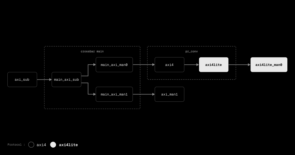
Accelerate SoC design with automated interconnect generation
The Omnibus interconnect generator has joined a broad portfolio of open source tooling developed by Antmicro that is aimed at boosting productivity for modern, agent-assisted silicon teams. Next to tools such as Topwrap, Busperf and sv-bugpoint, Omnibus can help you expedite the SoC design, debugging and optimization processes, also in AI-assisted and CI-driven workflows. With swappable frontends and backends, Antmicro can expand Omnibus with different sources or targets without recreating the entire tool, and customize it to your needs.
If you would like to learn more about how Antmicro’s tools and services can improve your SoC design workflows, reach out at contact@antmicro.com.