Increasingly more often, modern server integrators choose to rely on the flexibility of Open Compute Project’s DC-SCM (Datacenter-ready Secure Control Module) for server state observation and management. Its modular nature allows for easy scaling, maintenance, commissioning and modifications, as the module can be easily swapped, which opens doors for future upgrades and expansion. Baseboard Management Controllers (BMCs) such as DC-SCMs are crucial in order to ensure reliability of servers, and achieving a higher level of dependability may be accomplished by extending, upgrading and testing the BMC software, which you can do with the use of many of the DC-SCM tools that Antmicro has developed. For example, our DC-SCM Breakout Board can be used in desktop mode for software development and testing in a lab environment, providing a risk-free setting for development.
Once a DC-SCM board is connected to an HPM (Host Processor Module), two interfaces are used in the early stage of boot: LTPI and eSPI.
LTPI (LVDS Tunneling Protocol and Interface) is mostly used for low-speed control and management signals, usually in handling low-level maintenance. We’ve described LTPI features in our article about the 2.1 revision to Antmicro’s DC-SCM reference platform, which implemented the LTPI protocol into the said reference design.
In addition to LTPI, servers also utilize eSPI (enhanced Serial Peripheral Interface) - a standard developed by Intel to replace the legacy LPC bus. eSPI is a CPU management interface used in Platform Controller Hub-less (PCH-less) applications in order to establish a direct line of communication between the server’s CPU and BMC, and is therefore necessary in the server boot process. eSPI was integrated into the setup we showcased at OCP 2025, which was based on the Intel Lincoln City HPM. Continuing with our work on server development, we later managed to successfully boot a server thanks to our experience with eSPI integration.
To expand the possibilities of debugging and testing DC-SCMs even further, Antmicro developed several new open source tools for server debugging, this time focusing on the crucial eSPI interface: the eSPI Debugger, the DC-SCI Debug Interposer, as well as an eSPI decoder plugin for Logic 2. This article describes each of these new tools, as well as some recent modifications to our DC-SCM Breakout Board.
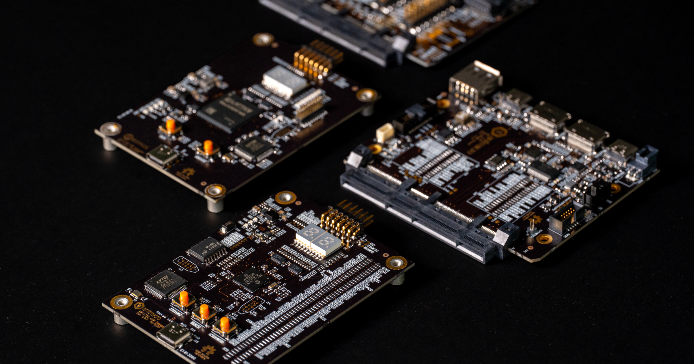
eSPI Debugger overview
The eSPI Debugger is a compact board which acts as a target device receiving eSPI signals from the server CPU. We’ve developed two versions of the adapter, based on the following hardware components:
The MEC1723 is a low-power integrated embedded controller containing a 32-bit ARM Cortex-M4F processor core - a dedicated chip for server management, capable of running Zephyr RTOS, for which we developed eSPI Debugger firmware that you can find here. The chip is equipped with an integrated eSPI interface operating up to 66 MHz, compatible with the eSPI Interface Base Spec, Revision 1.0, and eSPI Compatibility Spec, Revision 0.6. It provides security features such as Root of Trust (RoT), flash encryption and authentication, AES and SHA engines. It supports Controller Attached Flash (CAF) and Target Attached Flash (TAF), the eSPI Peripheral bus, Virtual Wires, Out-of-Band channels and Run-time Flash Access channels. Among its interfaces are the PECI Interface 3.1, the Port 80 BIOS Debug Port, and two instances of UART.
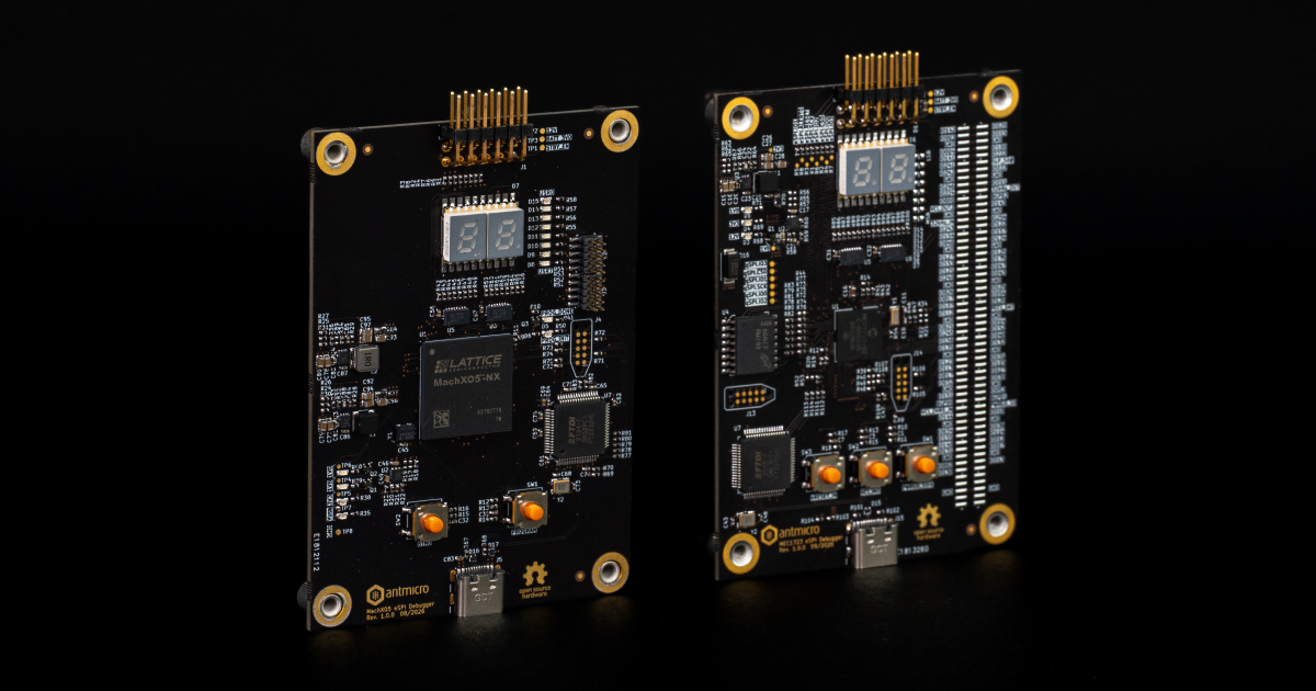
The MachXO5-NX is a low-power FPGA from a secure control product family, based on the Nexus FPGA platform using 28nm technology. It has up to 100K logic density, 7.3 Mb of internal memory, as well as 55 Mb of dedicated User Flash Memory (UFM), with LVDS, MIPI, and PCIe interfaces. For the development of the eSPI Debugger, we utilized Lattice’s eSPI IP Core, which we integrated into RTL. The strength of this particular device lies in its flexibility, as the interfaces can be reconfigured, replaced, or updated, as they’re IP cores of the FPGA, giving the design plenty of customization opportunities.
Oftentimes when coming across commercial and off the shelf debuggers, they may have rather significant drawbacks. They can be hard to obtain, have a high price tag, and they are typically closed source. The eSPI Debugger solves these limitations - it’s an open source solution for debugging the HPM boot flow which is freely available on GitHub as well as our Open Hardware portal, in a compact size of 87 x 62 mm (3.4 x 2.4 inch). The debugger displays HPM booting status with Power-on Self-Test (POST) LEDs for easy visibility and interactivity. The HPM CPU console, as well as eSPI Debugger’s own console are exposed via a USB-C port.
And for investigating the eSPI connection, we created a decoder plugin for the Logic 2 logic analyzer software, which is described in the following section.
An open source eSPI decoder plugin for Logic 2
Because eSPI is an interface used in very specific circumstances (such as the context of server boot), if there is a need for inspecting or debugging eSPI signals, the options for decoders or logic analyzers seem to be very limited. In order to provide the relevant software for eSPI inspection and debugging, Antmicro has now developed a plugin for Saleae’s software for their signal analyzers, Logic 2.
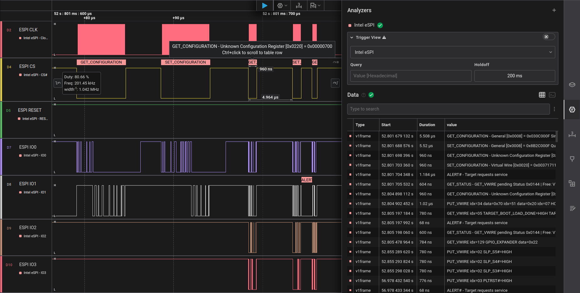
Logic 2 is used to capture, analyze, as well as decode signals from oscilloscopes and logic analyzers. Our plugin is a custom, low level analyzer for the Intel eSPI specification, developed using the Protocol Analyzer API and the 1.6 revision of the Enhanced Serial Peripheral Interface (eSPI) Interface Base Specification. The plugin can work alongside the eSPI Debugger in order to allow analyzing and debugging eSPI signals, as well as showing communication between the server CPU and BMC.
DC-SCI Debug Interposer
Another new tool we’ve developed in order to aid the debugging process is the DC-SCI Debug Interposer - a passthrough board meant for placement between the Host Processor Module (HPM) and the DC-SCM. The Interposer has a PCB outline of 68 x 90 mm (2.67 x 3.5 inch), two BIOS SPI Flash sockets, as well as a 2-port USB controller connected to the PCIe channel. It is compatible with the DC-SCM 2.1 specification.
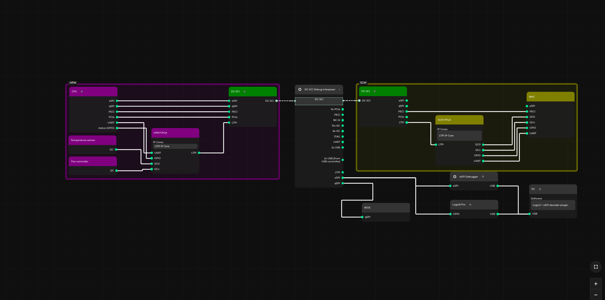 For an interactive version of the diagram, visit the desktop version of the website.
 The DC-SCI Debug Interposer exposes all Secure Communication Interface (DC-SCI) low-speed signals on the 2.54 mm GPIO headers, allowing for injection of signals into a server’s DC-SCM or monitoring the signals without their disruption. The BIOS SPI Flash sockets make it possible to attach the BIOS directly to the HPM. Additionally, jumper resistors mounted on each line allow to disable the connection of specific interfaces between the HPM and the DC-SCM.

Pairing the DC-SCI Debug Interposer with the eSPI Debugger creates a setup for debugging eSPI signals, eliminating the need to reroute or reconnect anything to use the debugger. It serves as a convenient way to connect the Interposer to a logic analyzer and, for example, enables quickly swapping between DC-SCM boards in order to compare their signals.
Booting a sample server and revising the DC-SCM Breakout Board
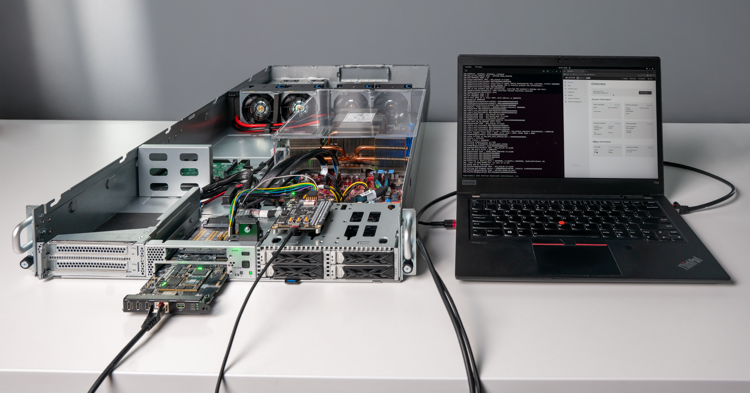
As mentioned in the beginning of this article, eSPI is an essential part of the sever booting process, being responsible for handling keyboard or controller I/O, power management events, firmware flash memory access, as well as exposing the CPU console for configuring BIOS. Ensuring that eSPI works correctly was a crucial element in our work to boot up a sample server; as such, we implemented the Virtual Wire handling according to the eSPI specification, exposed the eSPI tunneled console on USB(UART) and POST LEDs on a 7-segment display. With these implementations, we successfully managed to initialize the server - you can see the setup of the booted up the Intel Birchstream Reference platform featuring Intel Xeon 6 series CPU presented in the photo below.
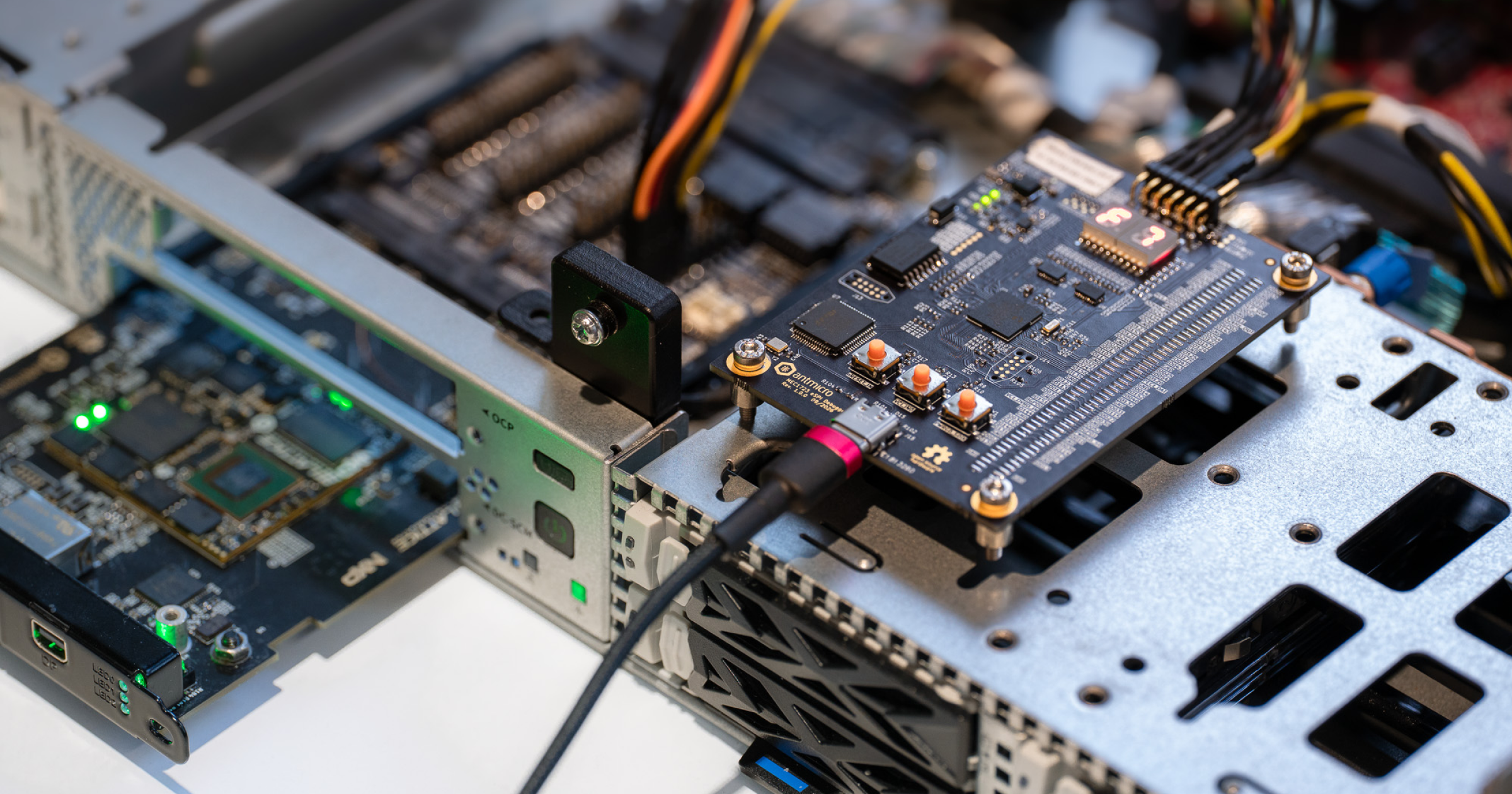
We’ve also made another modification to the DC-SCM Breakout Board. The board is a tool which exposes DC-SCM interfaces, making it a convenient platform for software development, the debugging process, and initial pre-deployment validation. Just like our other DC-SCM solutions, it’s compatible with modules which follow the DC-SCM 2.1 specification. The newest 2.2 revision adds a third OCuLink connector for the PCIe Endpoint, which in the DC-SCM Common Circuit Type 1 is reserved for USB Controllers. This particular modification allows for more thorough testing of the USB controllers on the DC-SCM boards we develop.
Server boot and management with Antmicro’s DC-SCM solutions
Our newly introduced eSPI debugging tools can provide users with a more complete development setup for servers that use DC-SCM. Complete with the DC-SCM Breakout Board, the eSPI Debugger, eSPI decoder plugin, and the DC-SCI Debug Interposer allow for gathering, analyzing, debugging and testing of eSPI signals in a controlled environment, in order to verify eSPI functionality prior to connecting a DC-SCM board into a server.
Antmicro has years of experience helping customers with the development of hardware for datacenters, offering a variety of open source tools for comprehensive testing such as Protoplaster for automatic hardware and BSP testing, the Rowhammer Tester, the flagship Renode framework for simulation-driven software development, and many more. If you’re interested in a custom DC-SCM board, or tooling for a specific use case, reach out to as at contact@antmicro.com.
And, if you’re attending the 2026 OCP Global Summit in San Jose, CA on October 12-15, be sure to visit us at the Innovation Village, where Antmicro, together with Altera, will be showing a demonstration of our recently released Modular Agilex 5E DC-SCM Carrier Board!