Antmicro’s Renode framework provides users with a multitude of features for simulation-driven product development and testing, ranging from pre-silicon prototyping, through software development on virtual hardware, to late-stage design validation. Many of our customers who use Renode utilize it for its co-simulation capabilities - from RTL co-simulation with tools such as Verilator and recently improved SystemC integration, to various world-state simulators allowing you to elaborate testing and verification scenarios with industry-specific physical factors, e.g. in the automotive or space context.
To even further expand Renode’s advanced co-simulation options, Antmicro has now upgraded the framework’s External Control API. This article describes a variety of new interfaces we added and those we improved, a modification to the API protocol, as well as the newly supported Renode-Renode co-simulation, which we showcase in a demonstration using Google’s RISC-V-based Coral NPU.
Unifying the programmer’s API and hardware interface improvements
To make Renode’s API easier to use overall, we’ve unified some of its elements - for example by adding common types, such as renode_time_t. Common types not only improve the readability of the API code, but also provide uniformity, which is beneficial for modification and maintainability.
The API provides several hardware interfaces - our latest work improves the interfaces we have implemented previously, as well as introduces several new ones. Currently, the available interfaces are: ADC, SPI, CAN, System Bus, Signal, Bus Peripheral, Time Elapsed, and Custom Command. Most of the interfaces allow for defining a custom callback, specific to the interface; additionally, certain interfaces also add new functions when triggering particular commands manually. The following sections outline each of the interfaces and their functionality. A full reference of the available functions and types can be found in the External Control API documentation.
Controling and synchronizing the simulation
Time progression can be managed in two ways: a client can advance Renode explicitly with renode_run_for or follow Renode’s time updates through the Time Elapsed callback and advance its own timer accordingly.
Run For
renode_run_for advances the simulation by a specified duration of virtual time. For example, the client can apply a sensor input, let the firmware run for 10 ms, and then inspect its response:
renode_time_t duration;
if ((error = renode_create_time(10, TU_MILLISECONDS, &duration)) != NO_ERROR) {
    goto fail;
}
if ((error = renode_run_for(renode, duration)) != NO_ERROR) {
    goto fail;
}
Time Elapsed
Alternatively, the client can follow Renode’s virtual time through the Time Elapsed callback. In this mode, Renode manages the flow of time, notifying the client after each simulation quantum so it can advance its own model to the reported timestamp.
The callback presented below prints the current virtual time. A co-simulation client could use this timestamp to advance its external simulation.
static void time_trace_callback(void *user_data, renode_time_t *time)
{
    const char *machine_name = user_data;

    printf("%s: simulated time = %.6f s\n",
           machine_name,
           renode_time_to_seconds(*time));
}
Time Elapsed allows you to synchronize Renode’s virtual time with external simulators, such as RTL simulations or a physical environment model, ensuring that events happen at the correct time. And, with virtual times synchronized, you can trigger events after a set period of time has passed - such as triggering an interrupt, injecting a fault, or setting a specific sensor value.
Custom Command
The Custom Command API provides a client callback to receive an arbitrary string command from Renode, sent using the SendCustomCommand keyword. Moreover, it also has a function to send a custom command to Renode, which is then executed in Renode’s Monitor.
Below, we show an example command handler for controlling a simulated environment value in an external simulator:
static renode_custom_command_response_data_t *sim_command(void *user_data, renode_custom_command_event_data_t *event)
{
    simulator_t *sim = user_data;
    float temperature;

    if(sscanf(event->command, "sim temperature %f", &temperature) == 1) {
        simulator_set_temperature(sim, temperature);
        return make_response(true, "Temperature updated");
    }

    return make_response(false, "Use: sim temperature <degrees>");
}
This interface can enable Renode Robot Framework tests to send commands to an external client or simulator, controlling elements of the external simulation; it could be used for introducing changes to the simulated environment, running client-side checks, or for signal-specific milestones in the test scenario.
Memory-mapped interfaces and signals
These interfaces let an external client emulate hardware components by handling memory-mapped accesses and exchanging signals, including GPIOs and interrupts, with the platform simulated in Renode.
Bus Peripheral
Renode’s API already had an implemented SYSTEM_BUS command, allowing to perform access on the system bus. The new Bus Peripheral interface expands on it to support external hardware modeling at the SoC level. It allows for defining regions on Renode’s system bus and directing accesses within the defined ranges to specific callbacks implemented on the client side.
When registering a callback, you may select only certain widths (byte, word, double word, quad word, multi-byte) or only certain types (write, read, both). Moreover, the interface provides an event which is sent on every access (write or read) to a specific region in the memory map, which is defined in the platform definition.
Note that the callbacks can only be registered to peripherals which are present in the Renode platform description - they can be defined in the .repl file as follows:
counter_bus_peripheral: Bus.ExternalControlBusPeripheral @ sysbus 0x50000000
    size: 0x4
Below, we show an example callback that is used to model a simple counter register, returning a value incrementing on each read.
#define COUNTER_REGISTER 0x50000000u

typedef struct {
    uint32_t value;
} counter_device_t;

static void counter_callback(void *user_data, renode_sysbus_event_data_t *event)
{
    counter_device_t *dev = user_data;

    // Reject unaligned accesses
    if (event_data->address != COUNTER_REGISTER) {
        return;
    }

    if(event->access_type == SYSBUS_CB_READ) {
        uint32_t value = dev->value++;
        memcpy(event->data, &value, sizeof(value));
    } else if(event->access_type == SYSBUS_CB_WRITE) {
        memcpy(&dev->value, event->data, sizeof(dev->value));
    }

    event->access_succeeded = true;
}
The callback can be registered using renode_get_bus_peripheral and renode_register_sysbus_access_callback:
  renode_bus_peripheral_t *counter_bus_peripheral;
  if ((err = renode_get_bus_peripheral(machine, "counter_bus_peripheral", &counter_bus_peripheral))) {
    goto fail;
  }
  if ((err = renode_register_sysbus_access_callback(counter_bus_peripheral, SYSBUS_CB_BOTH, AW_DOUBLE_WORD, &counter_dev, counter_callback))) {
    goto fail;
  }
If, instead of registering specific peripherals for each exported address space region, you’d want to handle routing between peripherals on the client side, you can use the following syntax:
external_bus: Bus.ExternalControlBusPeripheral @ {
        sysbus 0x40000000;
        sysbus 0xc0000000;
    }
    size: 0x40000000
The two registration points each cover 1 GiB: 0x40000000 to 0x7fffffff and 0xc0000000 to 0xffffffff. A single callback can route accesses based on its absolute address to different devices in the external client:
static void bus_access_callback(void *user_data, renode_sysbus_event_data_t *event)
{
    if(event->address >= 0x40000000 && event->address < 0x40001000) {
        handle_timer_access(user_data, event);
    } else if(event->address >= 0x50000000 && event->address < 0x50001000) {
        handle_dma_access(user_data, event);
    } else if(event->address >= 0xc0000000 && event->address < 0xc0001000) {
        handle_uart_access(user_data, event);
    } else {
        event->access_succeeded = false;
    }
}
In this example, handle_timer_access, handle_dma_access, and handle_uart_access are custom handlers that process the accesses within their respective ranges. To route reads and writes of all supported widths, register bus_access_callback on external_bus using renode_register_sysbus_access_callback with SYSBUS_CB_BOTH and AW_CB_ANY.
Signal API
With the Signal interface, we introduced the renode_get_gpio_state and renode_set_gpio_state functions, which allow to fetch as well as set the state of a specified signal. Additionally, users are able to receive a callback whenever the state of a given signal undergoes any change. An example callback looks as follows:
typedef struct {
    const char *machine_name;
    const char *gpio_name;
    int pin_number;
} gpio_logger_t;

static void gpio_log_callback(void *user_data, renode_gpio_event_data_t *event)
{
    gpio_logger_t *gpio = user_data;

    printf("%s: %s GPIO %d at %" PRIu64 " us\n",
           gpio->machine_name,
           event->state ? "set" : "cleared",
           gpio->pin_number,
           renode_time_to_time_unit(event->time, TU_MICROSECONDS));
}
GPIOs allow for simulating external inputs. With the use of an external UI or an automated test, the GPIO interface can be used for testing buttons, switches, or rotary encoders, giving access to interactive testing without requiring physical hardware. Moreover, it lets users monitor GPIO outputs used for LEDs, resets, or chip-selects - an external client can log, visualize, or verify the changes in the signals.
The same mechanism also represents signals between simulated components, such as interrupt sources. For example, an external DMA can signal transfer completion to a simulated interrupt controller.
Interfacing with external devices through API
Aside from supporting SoC peripherals and distribution of the address space between simulators, Renode can also expose peripheral interfaces to interact with physics simulators, traffic analyzers, or real-world hardware.
ADC API
The ADC interface lets an external client read and set the input voltage of a channel on a simulated ADC. renode_get_adc obtains the peripheral handle, and renode_get_adc_channel_count returns its channel count. renode_get_adc_channel_value and renode_set_adc_channel_value read and update a selected channel, with voltages in microvolts.
The following example reads the current input voltage in a temperature sensor, then sets its output to represent 80°C. This can be used to test temperature threshold detection. The temperature_to_uv helper converts the temperature to microvolts using the sensor’s voltage mapping:
uint32_t voltage_uv;
if ((error = renode_get_adc_channel_value(adc, channel, &voltage_uv)) != NO_ERROR) {
    fprintf(stderr, "Reading ADC voltage failed with: %s\n", get_error_message(error));
    goto fail_adc;
}
printf("Initial ADC input voltage: %" PRIu32 " uV\n", voltage_uv);

if ((error = renode_set_adc_channel_value(adc, channel, temperature_to_uv(80))) != NO_ERROR) {
    fprintf(stderr, "Setting temperature failed with: %s\n", get_error_message(error));
    goto fail_adc;
}
By changing the input voltage, an external environment model can represent changes in temperature, light, pressure, or other sensor readings. This allows firmware to be tested against gradual changes, thresholds, noise, and sudden events.
CAN
Another new API we added is the CAN interface. Its new peripheral, CANExternalControlBus, acts as an adapter between an external client and Renode’s CAN network. Connected to the same CAN hub as a simulated ECU’s CAN controller, it forwards received frames to the client’s callback and injects frames sent by the client into the network.
To expose a CAN network to the external client, add the adapter to the machine’s .repl platform description:
can_external: CAN.CANExternalControlBus @ sysbusThen, in the .resc script, create a CAN hub and connect both the simulated controller and the adapter peripheral:
emulation CreateCANHub "canHub"
connector Connect sysbus.can canHub
connector Connect sysbus.can_external canHub
For more details on setting up CAN networks, see the CAN-based connections documentation.
After obtaining a handle to the adapter with renode_get_can, the client can send frames using renode_send_can_message.
In this example, a simple protocol defines ID 0x200 and payload 0x01 as a vehicle-status request:
uint8_t command[] = { 0x01 };
if ((error = renode_send_can_message(can, command, sizeof(command), 0x200)) != NO_ERROR) {
    fprintf(stderr, "Sending CAN command failed with: %s\n", get_error_message(error));
    goto fail_can;
}
To receive vehicle-status updates, the client registers a callback with renode_register_can_callback. The following callback decodes frames with ID 0x201, extracting the RPM and gear from their payload:
static void vehicle_status_callback(void *user_data,
                                    renode_can_event_data_t *event)
{
    /* Example protocol: ID 0x201, data[0:1] are RPM, data[2] is gear. */
    if(event->packet_id != 0x201 || event->packet_length < 3) {
        return;
    }

    uint16_t rpm = event->packet[0] | (event->packet[1] << 8);
    uint8_t gear = event->packet[2];

    printf("Vehicle status: rpm=%u, gear=%u\n", rpm, gear);
}
These operations allow an external simulator to exchange commands, status updates, and sensor data with CAN devices simulated in Renode, making it particularly useful for automotive use cases. The same interface can support hardware-in-the-loop testing, with an external client forwarding frames between Renode’s CAN network and a physical CAN bus. CAN, as well as SPI which we describe next, recently received dedicated traffic analyzers directly in Renode’s GUI, allowing users to view bus activity in a table, making it easy to inspect individual messages and flag anomalies for swifter debugging of automotive systems.
SPI
The new ExternalControlSPIPeripheral represents an SPI target whose behavior is implemented by an external client. The client obtains its handle with renode_get_spi and installs callbacks with renode_spi_register_callbacks. The transmit callback receives each MOSI byte and returns a MISO byte; the finish callback lets the client reset its transaction state when the transfer ends.
Add the target to the .repl platform description and connect it to an existing SPI controller, here named spi0:
spi_external: SPI.ExternalControlSPIPeripheral @ spi0In this example, we model a simple register target by registering two callbacks and their shared device state using the spi handle:
typedef struct {
    uint8_t command;
    bool have_command;
    uint8_t status;
} spi_register_device_t;

spi_register_device_t device = {0};
if ((error = renode_spi_register_callbacks(spi, &device, spi_register_transmit, spi_register_finish)) != NO_ERROR) {
    goto fail_spi;
}
The callbacks below use the first byte to select a command: 0x01 writes the status register, and 0x80 reads it. The remaining bytes provide write data or clock out the read response:
static uint8_t spi_register_transmit(void *user_data, uint8_t mosi)
{
    spi_register_device_t *dev = user_data;

    if(!dev->have_command) {
        dev->command = mosi;
        dev->have_command = true;
        return 0x00;
    }

    /* Command 0x80: READ_STATUS */
    if(dev->command == 0x80) {
        return dev->status;
    }

    /* Command 0x01: WRITE_STATUS */
    if(dev->command == 0x01) {
        dev->status = mosi;
    }

    return 0x00;
}

static void spi_register_finish(void *user_data)
{
    spi_register_device_t *dev = user_data;
    dev->have_command = false;
}
This interface lets an external client model sensors, memories, or radio modules used by simulated firmware. A client can also forward transactions to a physical SPI device for hardware-in-the-loop testing.
Modifying the API protocol for simpler use and complex scenarios
In addition to the many interface improvements, we also made significant changes to the API protocol itself. We modified the message format to enhance its readability and uniformity. The current External Control Message always consists of two elements: a header and an encapsulated message. The header is consistent for both requests and responses and is always the same size. Within the header is the message ID, as well as the message size. The most significant bit of the message ID indicates who initiated the request chain, with 0 for a server and 1 for a client.
The encapsulated message incorporates the command ID, the message type, and command data. The command ID identifies what command to execute (for example: time_elapsed, sysbus, or GPIO); the message type indicates whether the message is a request, a response, or an event. The last element is the command-specific data of varying length, such as the virtual timestamp, or a CAN frame.
The described message format enables to determine the message size without the need for fully decoding it, and the uniform header simplifies message parsing, as the header length is always the exact same regardless of message type. Moreover, the message has no subcommands - a specific command can be determined by the command ID without the need to parse the request; and the message ID allows to easily match each request to a response.
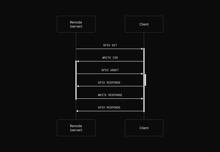
Additionally, we expanded the scope of nested requests, overhauling the logic to allow for the execution of complex scenarios without leading to deadlocks, and added a separate thread, which enables handling concurrent requests. While the main thread waits for a command to finish, another thread may then independently handle a request.
The overhaul of the protocol allows us to greatly expand the integration capabilities. While the current client API is implemented in C, we can prepare similar implementations in other technologies, depending on our customers’ needs.
Connecting two instances of Renode for Renode-to-Renode co-simulation
The changes and additions described in this article allowed us to implement client support in Renode - enabling for it to connect to a Renode server instance and run a simulation alongside the main instance.
Connecting two instances of Renode to each other requires to start the server in one Renode instance:
emulation CreateExternalControlServer "server" 1234Afterwards, all that is needed is connecting the client instance to the server:
# Connect to server
emulation CreateExternalControlClient "client" 1234

# Synchronize time with server Renode simulation
client SynchronizeTimeWithExternal

# Execute custom commands in Monitor
client AttachCustomCommandCallbackToMonitor

# Connect remote bus access from `counter_bus_peripheral` in the server platform to local system bus
client RegisterRemoteBusPeripheral "main-mach" "machine" "counter_bus_peripheral" DoubleWord ReadWrite
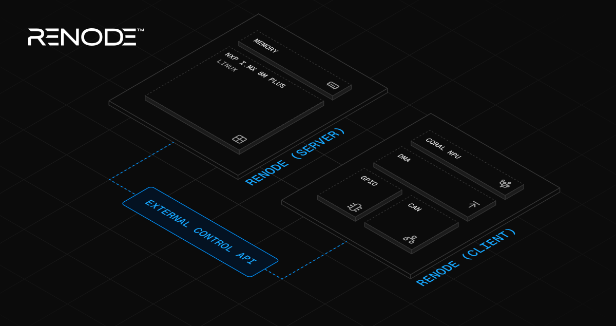
To demonstrate this feature, we’ve prepared a sample Renode-to-Renode connection scenario. The demonstration is based on an already existing Coral NPU demo - to showcase the new Renode-to-Renode capabilities, we simulated a scenario of an IMX8MP platform running Linux in Renode (as the server), which uses a Coral NPU and a simple DMA that runs in a separate Renode instance (as the client). Linux, running in the server instance, accesses the DMA as a memory-mapped device, and configures it by writing to DMA’s registers. The DMA then transfers data from the server instance’s memory into the Coral NPU’s local memory. The process behaves the same as a single simulation instance - the DMA appears as a memory-mapped peripheral, and Limux uses its registers to configure transfers, which is a transparent process for the software.
You can find the demonstration in Renode’s Github repository.
Incorporate Renode into your testing setup for complex co-simulation scenarios
With its improved API, Renode has even greater potential for co-simulation, enabling complex testing scenarios for your devices by making the process of working alongside external simulation software simple and user-friendly. Antmicro often works with customers on improvements and additions to co-simulation for their specific use cases.
If you’re interested in learning more about Renode’s co-simulation capabilities, possible integration with external IDEs and tools, or you would like Antmicro to help you adapt Renode into your flow to work alongside your usual tools, visit the Renode page and reach out to us at contact@antmicro.com.