In the process of building their next-gen products, customers who want complete control, transparency and customization often contract Antmicro to develop complex hardware designs, including application SoC baseboards or high-end FPGA-based ASIC prototyping boards. Through our numerous ecosystem-focused collaborations and extensive R&D we have been able to release a wide variety of open hardware designs, which often become the base for subsequent, even more advanced projects. But Antmicro’s hardware and product design process itself is perhaps even more interesting than the results. Fully based on open source tools, it allows us to bring a software-driven, iterative approach to hardware design, addressing the need for rapid and versatile prototyping in a collaborative cross-team environment, involving PCB and mechanical designers, software developers, external stakeholders, marketing and business development.
To showcase this open hardware design workflow and the capabilities it offers, we are launching the Open Hardware Portal, a continuously updated database of popular hardware components along with their photorealistic 3D models and Antmicro’s open hardware boards these components were used in.
KiCad for advanced open hardware design
One of the staples of our open hardware design flow is KiCad, an open source hardware design suite which - thanks to its adoption by organizations such as CERN - has been very actively evolving in recent years. Together with a plethora of helper tools and scripts, a powerful, scalable compute infrastructure and company-wide coordination of our hardware design efforts, KiCad allows us create such advanced devices as 12+ layer DDR5 testers or 900-ball FPGA baseboards with relative ease. This is all possible thanks to the KiCad’s use of open, transparent and textual file formats and its plugin system, which let us version the design data and process it in various ways, introducing external scripts for both interactive and Continuous Integration use. This results in consistent, traceable PCB design releases including always up-to-date assets that can be fabricated and matched to specific commits they originate from.
The openness of the KiCad file formats also allows us to take things a step further using Blender, the wildly successful open source 3D creation tool. By combining the automatically generated releases of the hardware design files with the visualization engine, we can provide photorealistic previews of the design in the making. We can also mock boards in different variants to discuss mechanical arrangements and get the general look and feel of the device as a whole, even at the early stages of the design process. This is particularly important for some of our customers’ products where we would design as many as several dozen unique PCBs with associated mechanics which would need to come together into a coherent whole.
Opening the hardware design process
A well-defined open hardware design provides not only schematics and layout information but also a set of technological constraints that need to be followed during the PCB fabrication process, as well as component lists, or Bills of Materials (BOMs). In the face of the continued supply chain issues, it has become more important than ever to keep track of the components used in a hardware design and their potential counterparts by maintaining BOMs tightly coupled with the schematics. The open format of the KiCad design files enables BOM entries to be tracked precisely, and all the components in our BOMs taken together constitute a database that we extend every time we release a new design.
Given the sizable, ever-growing collection of Antmicro’s open hardware boards and associated components, we decided it will be beneficial to our customers and the broad community to share the component database and enhance it with additional assets, such as Blender models. With this approach, it is possible to reuse the set of component Blender models to virtually reproduce the process of assembling physical prototypes. Using our expertise in hardware design, 3D visualization and CI, we developed an automated, Blender-driven flow for making photorealistic 3D renders of complex designs made with components from our internal database.
KiCad-Blender flow for automated render generation
Blender renders are generated from our open hardware designs using the same assets that are normally used for producing physical prototypes. We utilize the extended Python-based Blender API which provides access to the majority of Blender controls, GUI elements, scene objects and internal rendering mechanisms. We use Gerber files generated from the PCB layout done in KiCad to define the PCB outline in a Blender scene and add top/bottom tracks, holes, vias, and component pads to it. The process of generating the PCB on a Blender scene is automated with a Python script which parses the input Gerber files directly or processes .png or .svg files derived from Gerber files. Gerber files are also used for generating textures and displacement maps which in turn sculpt the top and bottom side of the Blender-generated PCB surface.
Blender’s built-in 3D Boolean operations allow us to define openings, fastening holes and advanced cut-outs in the PCB surface based on their definitions from Gerber files. The Bill of Materials is used to identify Blender models of particular components that will populate the virtual PCB. Using the Pick and Place files generated from KiCad we can determine the locations and rotations of particular components on each side of the PCB. Finally, we use Blender’s Python API to set up the camera location, lighting and background.
Blender offers an extensive and well-documented command line interface and thus can be invoked directly from the command line, without its graphical interface. It is possible to launch Blender with pre-loaded scene content and invoke a Python script which will call the Blender API functions and launch the final rendering. This means that the whole Blender rendering process can be wrapped in a Continuous Integration pipeline so that the board renders can be generated repeatedly with every commit. Blender allows CPU-based rendering, so no special CI server hardware is required to implement the flow. Nevertheless we have expanded our scalable hardware-software CI system called Scalerunner with GPU-capable nodes to speed-up the rendering process of multiple assets, animations and board view in parallel.
Blender also supports a variety of output formats, including SVG for interactive diagrams with custom modifiers such as wireframes - very useful for READMEs, documentation, marketing content and more.

Since the presented flow relies on PCB production and assembly files (and not directly on the design files themselves), it can be adapted to PCB design tools other than KiCad (of course with KiCad we have complete end-to-end automation and customizability which still makes it the preferred choice). The rendering process allows for visualizing boards whose designs are not open - as long as the Gerber files for such boards are available and there is a defined Bill of Materials, the board can be recreated virtually.
The presented flow combines automatically-generated PCB outlines with components that are selectively instantiated on the Blender scene. For documentation purposes, we can render the components in isolation, like we did to generate CPU and SoC renders for our Renodepedia project. We can also manipulate the components in order to create exploded views or board assembly animations.
Finally, since Python scripts are interacting with the Blender API to automatically construct a scene containing a board, the complete board can be saved in Blender as a single .blend file. We can then use this .blend file representing one complete PCB to create another assembly, e.g. by placing the board into an enclosure or simulating plugs being inserted into sockets located on the board.
We can also daisy-chain the rendering process, so in the end we can take a look at composite drawings made of several boards, enclosure parts, and connectors assembled into a single device. Producing such composite drawings and animations can greatly speed-up cross-team cooperation. With the ability to create Blender renders from PCBs defined in KiCad, we can also mock potential solutions and discuss them with our customers at the very beginning of the design process, reducing the number of PCB iterations and simplifying mechanical integration.
We used this flow to automatically generate board and component renders for the Open Hardware Portal.
Open Hardware Portal: an extensive component database
Hardware is modular by nature, and reuse of specific components or even entire subsystems (based on reference designs) is a typical - and recommended - approach. Antmicro’s Open Hardware Portal showcases how specific components can be reused across many diverse projects and presents close-ups of specific components used in a design by sharing component 3D models in the Component view.
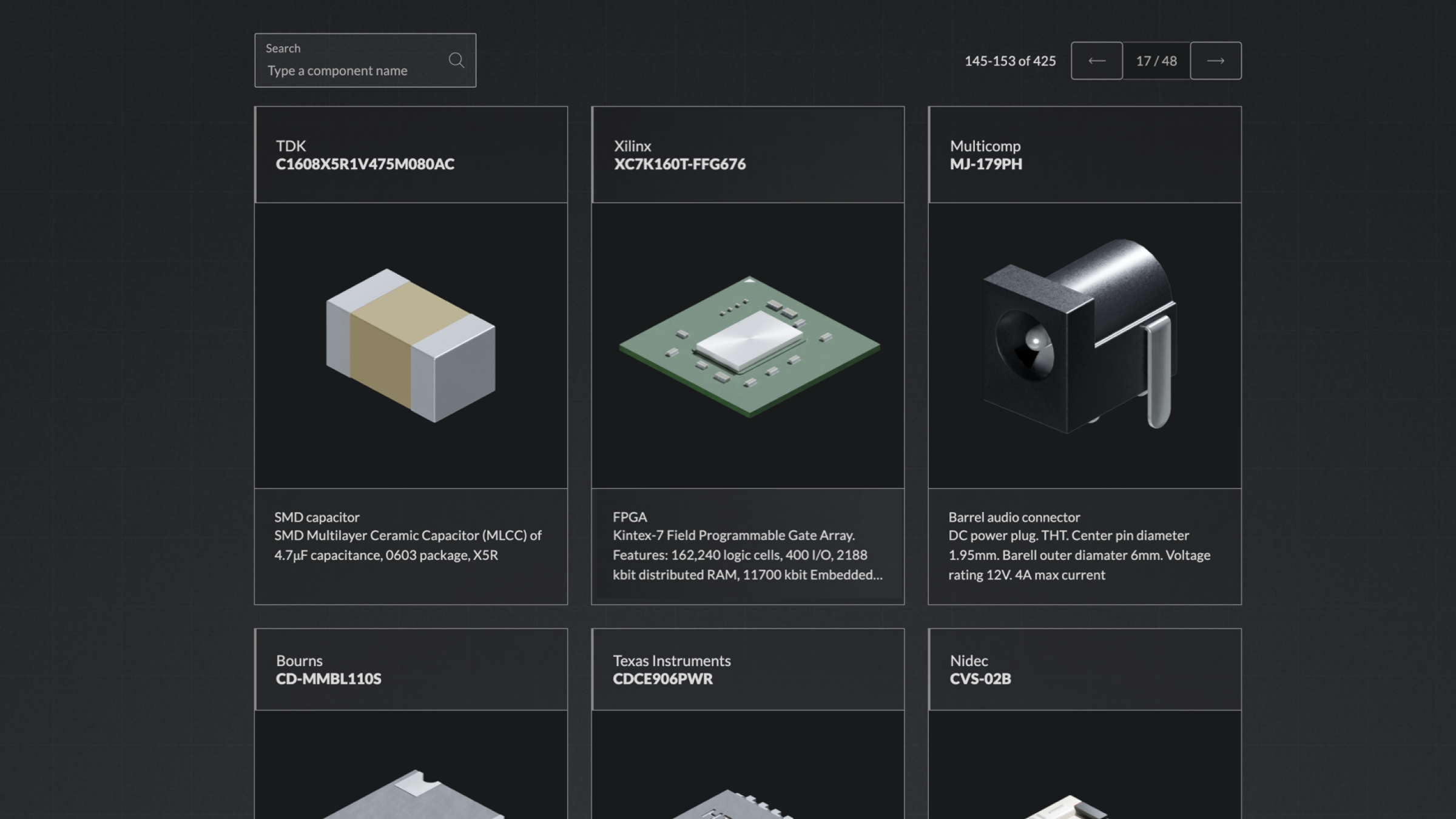
The Component subpage provides a list of hundreds of components, grouped based on their generic type. At the top of the list there is a search field for easier navigation and soon you will be able to navigate through the components more easily using advanced filtering and component grouping we are currently adding. On this page, each component is defined by its Manufacturer (MFR) and Manufacturer Part Number (MPN) which uniquely identify the component.
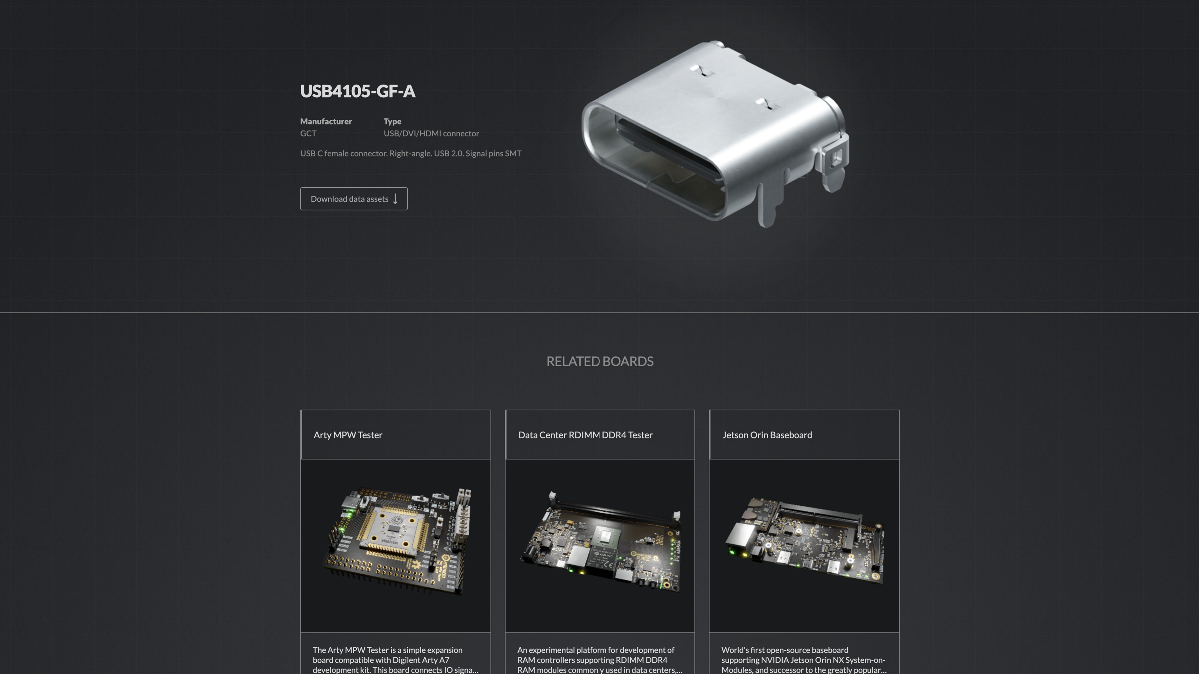
A single component view, for example a USB4105-GF-A right angle USB C female connector, provides a description as well as downloadable assets - .zip files containing, for now, the .blend model of the component. We’re currently working on adding the associated KiCad schematic symbol and PCB footprint. At the bottom of the page you can see related boards, showcasing real-life projects the component was used in.
Putting the components to use in real projects
The Boards subpage of the Open Hardware Portal provides a continuously expanding list of some of Antmicro’s open hardware projects. For each item on the list, there’s an animated 3D render generated with Blender, presenting a specific device en face when hovered over.
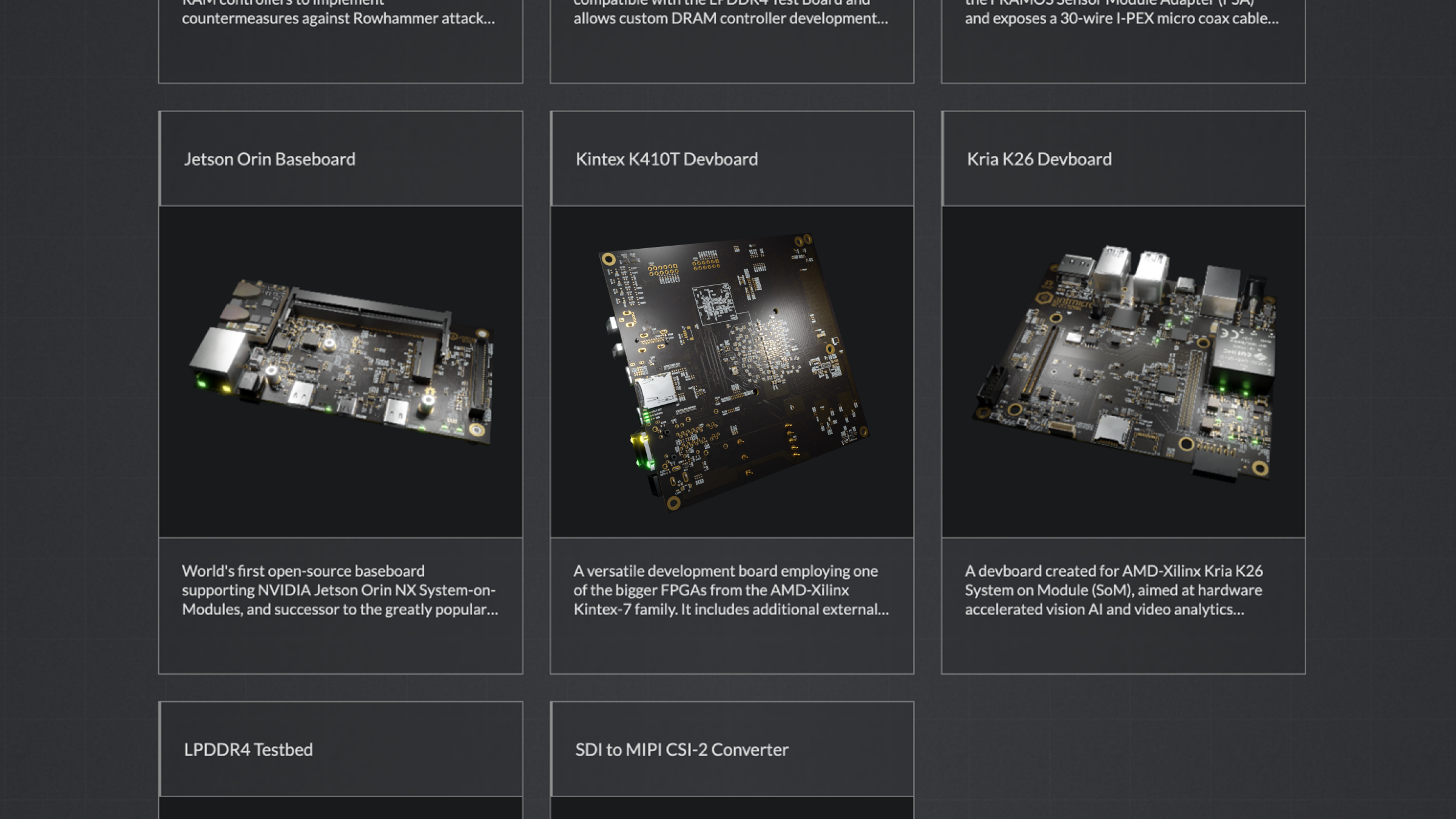
After choosing a board, for example the recently released Jetson Orin Baseboard, you’ll see a detailed description with links to outside resources, such as GitHub repos, Antmicro blog notes or the Open Source Portal. You’ll also find more animated renders showing the board from multiple angles.
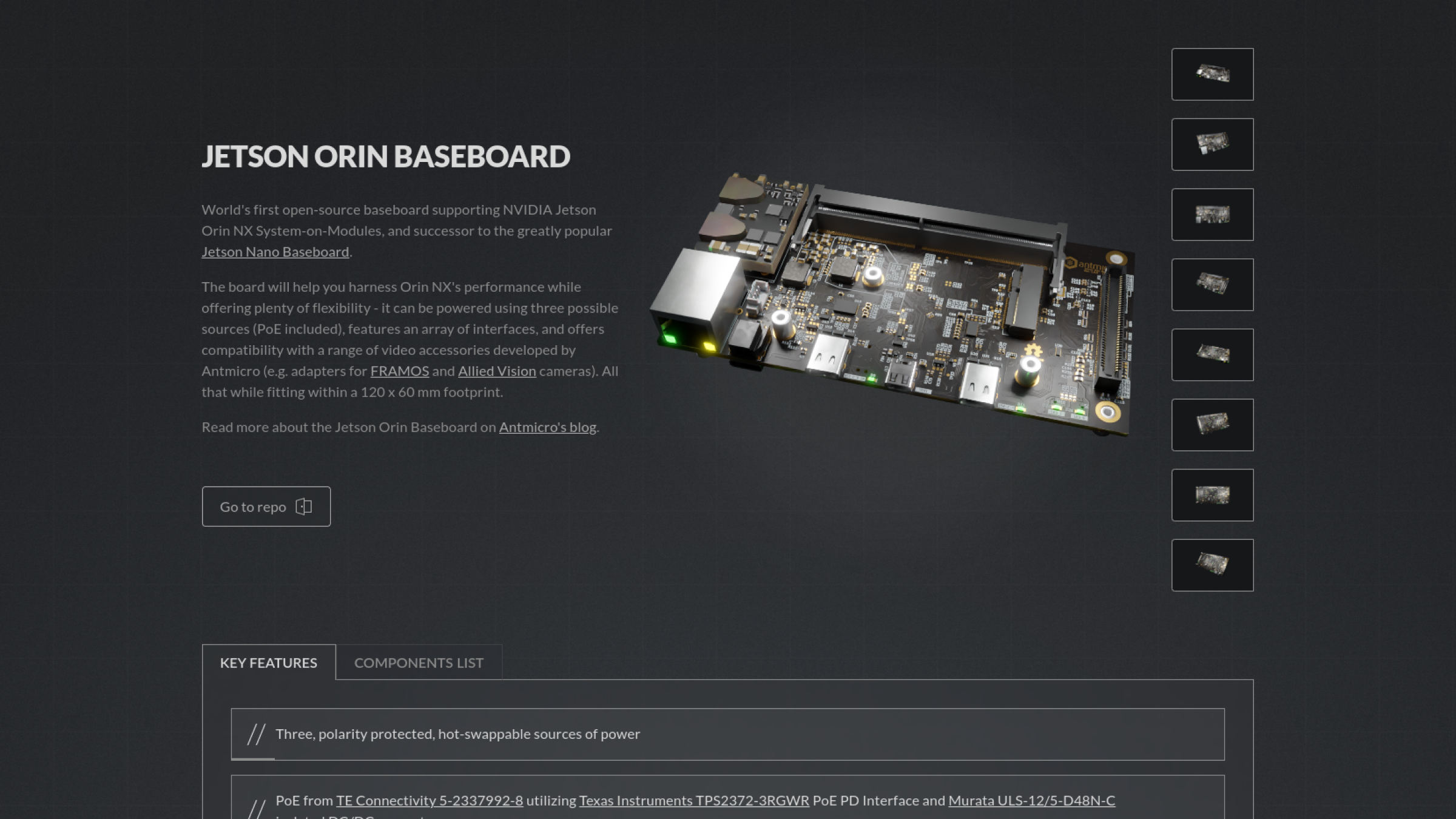
Below the description, there are two tabs. The first one, key features, provides a list of the major processing blocks, interfaces and connectors used in the design. Where available, the features cross-reference the components which implement them.
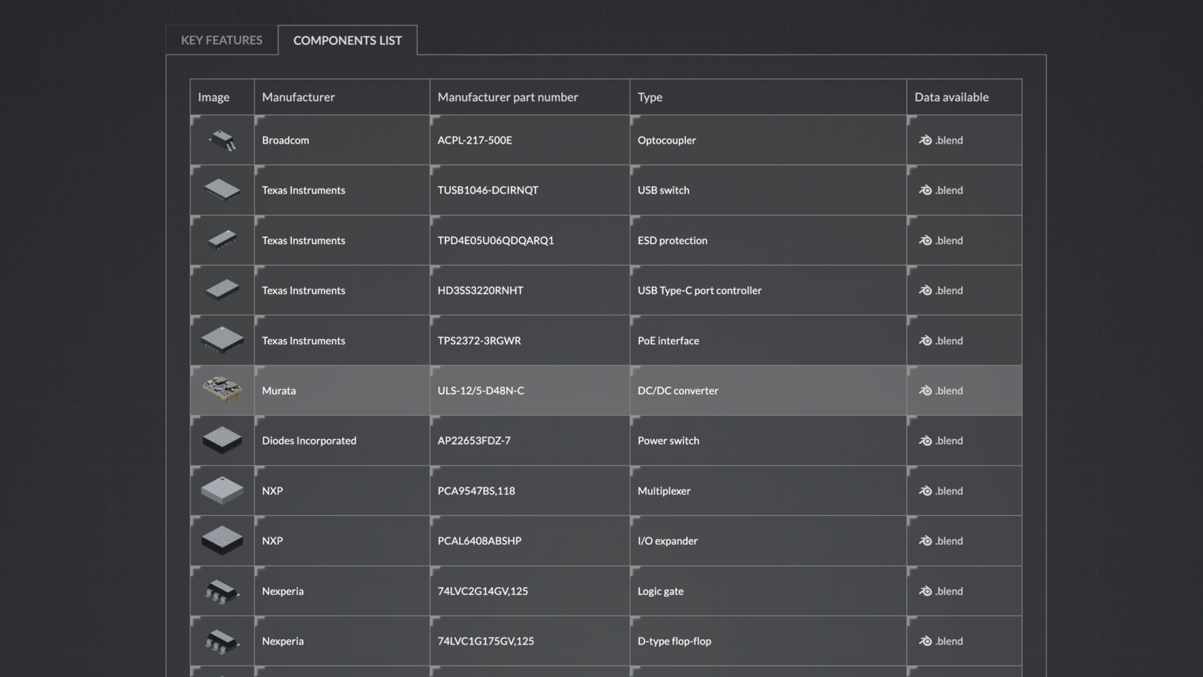
The second tab contains a list of components used in a particular design, i.e. a 3D render, manufacturer information, part number and type, and downloadable Blender data. After clicking a component, you’ll be taken to the component’s page where you can see more details.
The related boards section at the bottom of the page lists related projects which share components or implement similar functionalities.
Next steps
The Open Hardware Portal is being actively expanded - for one thing, we’re working on adding even more components and open hardware projects we have created over the years. But perhaps more importantly, we are also planning to provide additional assets, such as automatically generated block diagrams and stackups of the boards, mechanical drawings with board dimensions and simplified (wireframe) views of the more important components. We believe that automatically documented open hardware designs offer transparency and can be easily reused and integrated into new devices which we design and build for our customers.
The CI-driven hardware design flow combined with automated releases and version tracking enable extreme flexibility and rapid development capacities as well as an unprecedented ability to collaborate across teams and with our customers. The workflow can also be adopted for entire families of hardware designs and integrated with cloud or internal infrastructure. Reach out to us at contact@antmicro.com if you want to benefit from the fully open KiCad-Blender flow - we can help with every stage of your next hardware project’s design.


