Customers interested in building new industrial or consumer devices, typically involving one or more PCBs and based on Linux, Zephyr or Android (or even all of them at the same time), often approach Antmicro before they know what exact components they want to use. Such projects typically begin with a block diagram, and interestingly, across the industry there is no unified and structured way to collaborate at this stage of the project, before an actual schematic of a system can be produced and before the final choices in terms of platform, I/O, software etc. are made.
In an effort to change this status quo, with this note we are pleased to introduce the Visual System Designer, an open source tool announced at EOSS in Prague earlier this year, based on Antmicro’s open source component and platform database, whose goal is to enable a visual, formalized way to build embedded systems from well-defined building blocks. Integrating with Zephyr, Renode, Kenning and other open source frameworks that organize the embedded devices landscape, this public release of VSD is a first step towards providing a comprehensive and standardized methodology for rapid and flexible development of hardware-based products and systems.

Why structure matters
Without tooling specifically designed for reasoning about high-level components of a system (other than highly-formalized and rigid approaches originating in the business world), engineers will use a combination of diagramming tools or general-purpose graphic editors, email, chats and docs to try to express their intentions and debate potential options. Because of this, projects typically don’t get a machine-readable, formalized description of their components and building blocks up until the schematics stage, and even that is still not very useful from other, more software-centric perspectives.
From our work with structuring data as part of projects like Zephyr and Renodepedia, we have learned that there are many benefits to formalizing your system description: most tangibly, over 280 enabled platforms with over 1000 working Zephyr and U-Boot demos regularly tested with Renode in the Zephyr Dashboard CI showcase the power of automation. As the “block diagram problem” has been on our minds more and more often, at the same time we have been working on a visual diagramming tool for AI purposes, released this spring, whose potential for reuse in other fields coincided with the frustration described above. The tool’s modular design and extendibility allowed us to take the concept of hardware block diagrams much further than originally expected, serving as an inception point for the Visual System Designer, or VSD for short.
In this article, we will delve into how VSD was made possible, how it simplifies the process of building devices from beginning to end, and how it ties in with other parts of Antmicro’s toolkit to create a truly open embedded ecosystem where a reusable system description can be used to prototype hardware, generate firmware and simulation files, and more.
Various fields, a single framework
The Visual System Designer is a project made possible by bringing the work of all engineering teams at Antmicro together. Its genesis, GUI and UI principles were developed by our AI team for designing, visualizing and running AI optimization and runtime flows with Kenning, our open source AI framework.
Behind the scenes, the VSD framework takes advantage of the automated, CI-driven HW design flow which lies at the roots of Antmicro’s recently launched Open Hardware Portal. You can read about the flow and the portal itself in another one of our blog notes.
The database of hardware components, blocks, SoCs, and entire boards that users have at their disposal in VSD is based on a constantly growing collection of components used in Antmicro’s hardware designs. It is combined with Renodepedia which takes advantage of Zephyr’s structured data and catalogs all boards supported by the RTOS along with the hardware blocks that comprise them. Systematizing this substantial amount of data lets us observe patterns that help build embedded systems more efficiently, e.g. which drivers are already part of mainline Zephyr and which ones need to be added, or what components work best in particular use cases.
Antmicro is also currently working to extend the functionality of the Zephyr Dashboard to other OSs, starting with U-Boot, to be followed by Linux. The front end, the back end, and the structured data combined with Antmicro’s years of experience in the fields of embedded systems development, FPGA and ASIC design, prototyping, and verification allowed us to develop a framework that lets manufacturers and customers collaborate, reason about the systems they are building, and aids in prototyping.
Design hardware blocks, SoCs, and entire embedded systems
VSD uses a unified specification file containing different component types as aggregated from various sources of structured HW data. The structure of the framework allows us to ensure compatibility between and within HW designs through machine-readable characteristics assigned to each individual component e.g. matching of I/O types, interface counts etc.
The core Visual System Designer use case lies in combining SoCs, modules, sensors into complete devices or device systems (a few example boards are shown on the welcome page - click around to explore them). Besides the diagram itself, VSD shows you a searchable sidebar of available components, and that is where the real power lies; over time we want to enable all possible components - both in terms of SoCs, I/O, peripheral devices, sensors, conversion chips etc. - so that you can build completely arbitrary systems.
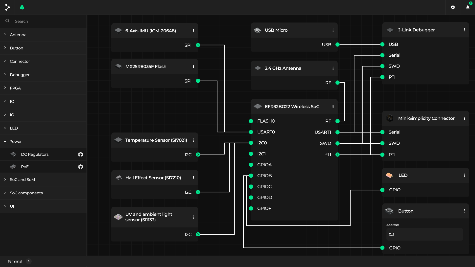
The components can be either generic (representing more of a block diagram, ideal component of a particular kind) or real-world chips, which also feature renders taken directly from our component database. Where available, components also refer to Renodepedia and the Open Hardware Portal so that users can download datasheets, KiCad footprints, browse memory maps and more.
When run locally, VSD can be used with a backend to generate device trees for arbitrary devices, which can be used for many other aims, as described in the section below.
One other use case for VSD, presented at the Barcelona RISC-V Summit is visually composing System-on-Chips from various hardware blocks available in the database through a graphical interface tool where users can select their desired IP cores and connect them together into SoCs of their own design. This capability, alongside the ability to navigate between the different abstraction levels (SoC, board, system) is currently in development.

Simulate, generate firmware, co-develop for ML
The formalized description is useful not just for building and brainstorming system architecture on a block diagram level, sharing device blueprints and researching component variants. As you may know from earlier blog notes, being able to produce a device tree or other kind of structured representation of the system can serve many practical purposes: from the ability to generate Renode simulation files using our device tree to .repl generator for functional simulation, through generating test Zephyr firmware specific to your particular design, up to - on a SoC level - producing a top level file or RTL simulation with Verilator.

Given its origin in the AI space, the framework is also obviously meant for hardware and software co-development for Machine Learning scenarios, taking advantage of the configurability and extensibility of RISC-V, provided by e.g. vector and custom instructions. Given the capability to run locally with a backend application such as Kenning, over time we will add features such as dropping edge AI models on top of an SoC/board, testing them in real-world scenarios with sensor data and gathering metrics from the execution of your AI pipelines.
The simplicity and freedom of the Designer combined with the ability to benchmark and optimize your AI flow with Kenning and the advent of open-source edge ML-acceleration hardware should constitute a paradigm shift in ML co-design.
Organizing the hardware ecosystem with open source
The Visual System Designer opens up the potential for vendors of SoCs, processing blocks and components to present their customers with their offering in a practically useful framework that lets them get to a working solution quickly. Bundled with a library of KiCad footprints, Blender 3D models and capabilities such as simulating in Renode or generating Zephyr firmware, we are hoping VSD will serve as a gateway to the hardware landscape that makes people’s lives easier.
If you are interested in working with Antmicro to build well-defined hardware systems, using the Visual System Designer to improve your HW/SW co-development workflows or adding your hardware to the VSD database, reach out to us at contact@antmicro.com.


